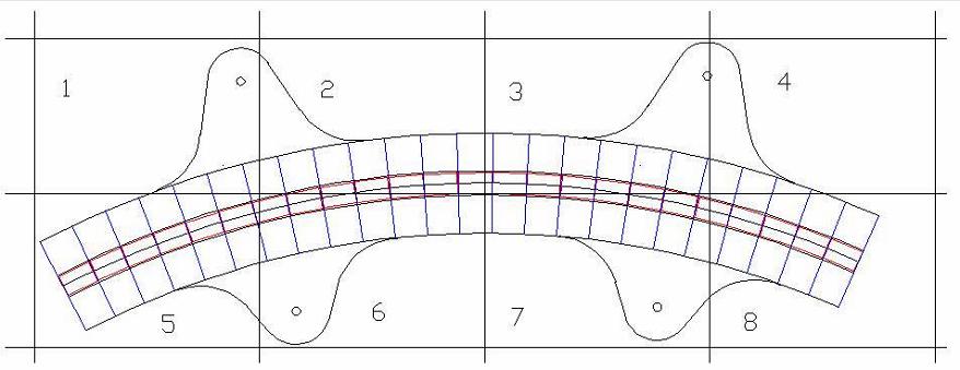
Machine Frame or Stator
Cross Section Construction Details
Cross Section Construction Details
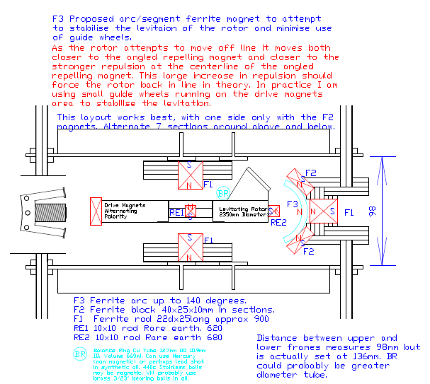
The Arc magnets have not been tried as no standard item could be found. Actual plywood construction details below. The locations of all assemblies is fully adjustable on the frame threaded rods. The design makes adding a second rotor relatively easy.
F1 Radial = 329 magnets. F1 Axial = 302 magnets .
F1 Radial = 329 magnets. F1 Axial = 302 magnets .
Distance 98 has been increased to 144. This give a clearance between axial magnet faces of about 38mm. The Radial magnets clearance is 27mm and this could perhaps be increased to about 35mm.
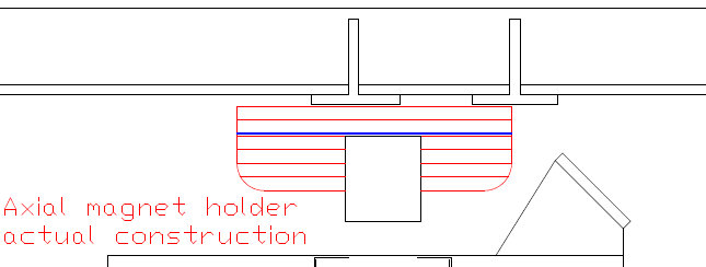
Blue sheet steel glued in place after the first 4 layers have been drilled out for the magnets. The steel holds the magnets in place temporarily. Radius corners routed later before magnets are installed.
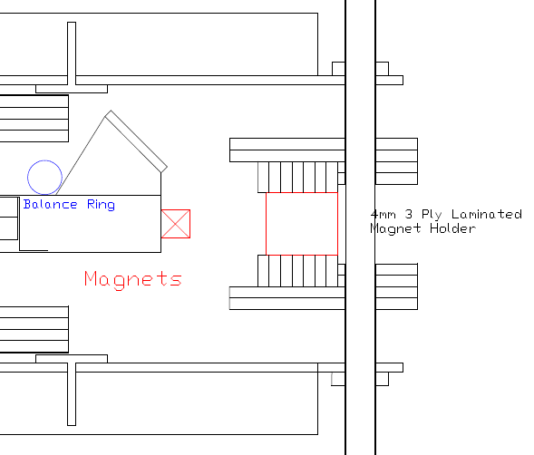
Radial magnet holder is constructed as shown from 4mm plywood ready for routing rebate for angled stabilization magnet installation. Each layer of all of these holders is made up of 10 arc sections with joints staggered.
Radial
Ferrite
Ferrite
Clearance between magnet faces
RE and Radial Ferrite is 27mm.
RE and Radial Ferrite is 27mm.
RE
This 27mm clearance is not adjustable. It has been altered from 15mm, and there is only 1mm between the threaded rod and the steel backing band. Any further increase would require moving all the outer frame rods outwards.
The clearance to remove or replace the rotor is very tight, as there is epoxy encasing the RE magnets. 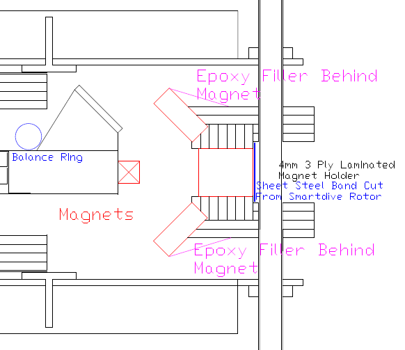
Radial magnet holder routed for angled stabilization magnets. Sheet steel band cut from a Smartdrive rotor holds magnets in place temporarily, and provides a little
extra strength for the assembly to resist the magnetic forces. The steel also seems to give a stronger magnetic field.
This assembly is held in place with washers and nuts top and bottom. A spacer is required in behind the steel band to allow for
tightening the nuts securely without distorting the assembly. Curved plywood sections should be attached in the space behind the steel band to prevent the band from being overstressed.
RE
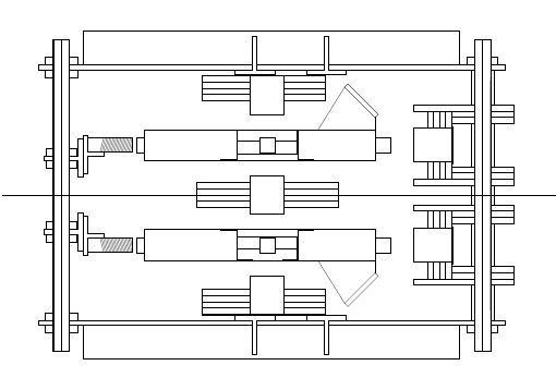
At the left is an elevation drawing of the
proposed complete motor assembly. It has
2 rotors, which will counter rotate. If this
machine works as intended, the 2nd rotor
proposed complete motor assembly. It has
2 rotors, which will counter rotate. If this
machine works as intended, the 2nd rotor
will provide stability. The frame will not attempt unwanted rotation. The only new
component to design is the center axial magnet holder.
component to design is the center axial magnet holder.
For a complete 2 rotor machine a possible center axial magnet holder comprised of sheet steel (2 layers ?) and plywood construction similar to the top and bottom magnet holders described above. The magnets used would be the same as used for the drive magnets, 40mm x 25mm x 10mm ferrites. The steel plate/s is used as reinforcing, and a row of magnets is attached on each side.
For the 3000mm machine, allowing 1mm gap between magnets, there are 216 magnets each side, 12 each side for each of the 18 frame sections. For the 2500mm machine being built now, allowing 1mm gap between magnets, there are 168 magnets each side, 12 each side for each of the 14 frame sections.
Three 4mm plywood layers are added each side to strengthen the component. The first of these layers each side would be the same outer shape as the steel, and the next 2 layers would be parallel curved strips. The magnets are installed with a hot glue gun, then secured with epoxy filler around and over. There should be very little stress on this component. The main problem could be heating from eddy currents, and this could also apply to other parts of the machine.
These magnets work out perfectly in size for both machines, so this center section could be made with a quite simple template. See below for 2500 Machine template overview.
