Machine Frame or Stator
Guide Wheels Locking Mechanism
Guide Wheels Locking Mechanism
The guide wheels retraction system now requires a locking mechanism to hold the wheels solidly in position at low speed. This uses an aluminum plate on each wheel arm, which is driven into place with a car door lock motor. To automate the startup process 6 Hall Effect sensors are used to ensure the locks are correctly positioned. More PCBs are needed for the sensors at each wheel, and another PCB for AND gates to combine the sensors into 3 pairs, and optocouplers as I have used the 12v Main for the sensors. This has become somewhat complicated, and requires more micro pins. I am now using a 40 pin micro, the Picaxe 40X2. This has 2 individual PWM timers and seems quite suitable for the job. The programming is no more complicated, and an excellent simulator is provided with the free software.
The locking function needs to know the rotational speed to work correctly. This is achieved by retrieving codes from the tacho Picaxe micro. This uses 3 outputs, which gives 8 codes. The first startup speed is zero, after that output codes are for ranges of speed.
For sequence testing, a small setup has been made ,using a rotary switch and 18 pin Picaxe to output the codes in the correct sequence. It has LED lights to visibly ensure the codes are correct. This will enable the complete program and mechanisms to be tested with the rotor stationary.
For sequence testing, a small setup has been made ,using a rotary switch and 18 pin Picaxe to output the codes in the correct sequence. It has LED lights to visibly ensure the codes are correct. This will enable the complete program and mechanisms to be tested with the rotor stationary.


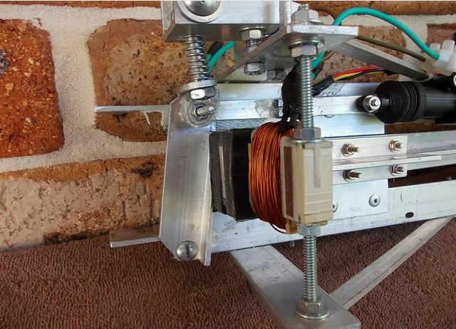
Above the lever arm magnet is latched against the steel core of the coil which extends the wheel towards the rotor. The aluminum angle piece is in the locked position. he spring near the top is an overcenter arrangement to control bounce in the locking movement.

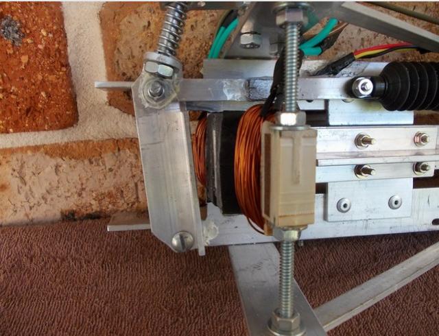
Above the lever arm magnet is still latched against the steel core of the coil which extends the wheel towards the rotor. The aluminum angle piece is now in the unlocked position. A small magnet can be seen directly above the coil, glued to the horizontal locking lever. Just behind and to the right is a Hall Effect switch (A3144). It is connected to the red, yellow, & black wires, and is glued to the frame with silicone. This sensor enables the micro to know the position of the lock.

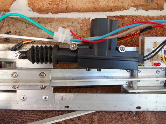
Six of the above aftermarket 12v car door locks are used, connected in opposing pairs.

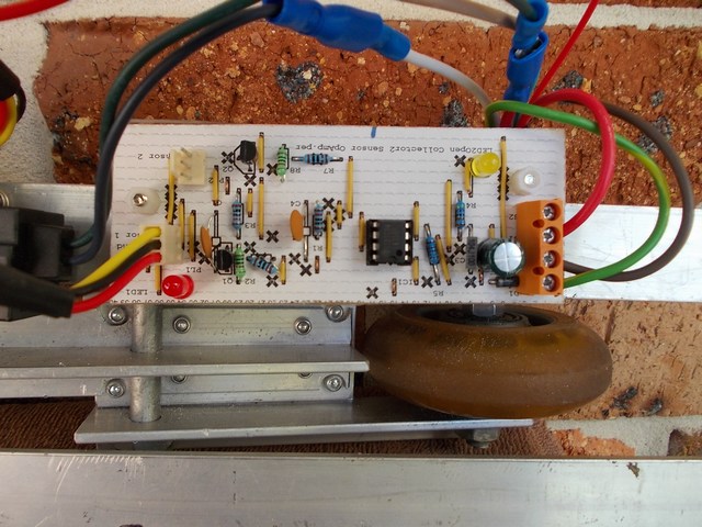
A small PCB is mounted on the wheel assembly to output the HE switch signal. This switch is low when near a mag field. I have used an OpAmp to convert to a high output. The board is built to enable two sensors to be connected if required.


