Machine Rotor Construction
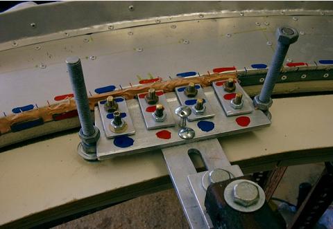
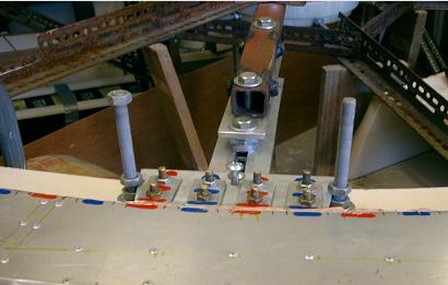
Drive Magnets Installation Jig
Drive Magnets Installation Jig


An aluminum jig is used to clamp the drive magnets into position. Epoxy is spread onto the rotor, and the jig is moved into position and locked until the epoxy sets. The jig is fitted to the table radius arm. The epoxy is then sanded smooth and the rotor is complete.
Note Sept 2012: The motor has been run slowly using these magnets. Because of the high switching speeds required to spin the motor with such short magnets, and avialability issues, I have removed and replaced the magnets with a much longer type. These are 40mm x 25mm x 10mm thick ferrites.
A set of 4 with same polarity facing out gives a length of 160mm, and have been fitted using the same jig and method.Another problem with the narrow magnets is if any vertical lift or acceleration occurs, the rotor
will/may lift away from the coils, and drive will be diminished. I am hoping the wider (25mm) magnets will allow more freedom of vertical movement. I retained the narrow steel backing strips, and this may have been an error as the coils do not like being moved far away from the centerline of the magnets.
If all else fails, it should be possible to make the coils move into alignment automatically.
A bonus is that the coils can be located much further away from the magnets. The air gap was 3mm
and now is about 10mm. Good clearance is handy with a fully floating rotor.


