
Experimental Machine 450mm Diameter
Levitating and Non Levitating Rotors
Levitating and Non Levitating Rotors
Two non levitating counter rotating rotors with a single row enhanced Halbach Array attached to each rotor. A fixed non magnetic alum conductor plate is located between rotors. There are 46 magnet arrays so the magnetic fields are alternating approximately every 20mm or 7.82 degrees of rotation. As the alternating fields from each rotor pass there will be a period with like poles in opposition. The fields will be forced to meet at a midway point in the thickness of the fixed conductor plate. As the rotors move to a point where unlike poles are in opposition, the magnetic fields will be attracted toward the opposite magnet. This should create an intertwining wave like motion. The velocity of the fields should be considerably increased in this way. Or perhaps one will cancel the other. The complete machine as shown weighs 14Kg
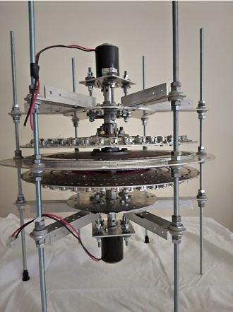
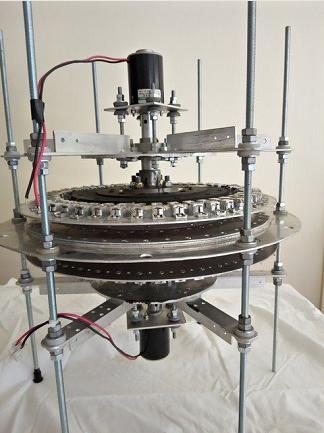
Test results for Sep 2012 show no result. The motors are brush DC 24v 30W 9k RPM unloaded. The rotors turn up to about 1k RPM each.
I will dismantle the machine and reassemble so the lower motor and rotor stay in the same position, but change the shaft for a full length version. The conductor plate will be able slide up the frame rods, and the central hub will be removed. The upper rotor and motor assembly will be absent. This arrangement is quite normal science, and should enable the conductor to lift if the magnets are powerful enough, and the rotational speed is sufficient. This seems to be a better way to test magnet / conductor combinations without making a complete machine. Any beneficial interaction between rotors would be easier to assess.
I have a vacuum cleaner motor and speed control which is much more powerful than the motors pictured. This should allow a greater rotational speed when fitted.The magnets should be able to be extended to a double row Halbach array. Perhaps the 80 arrays close together in alternating blocks may be worth trying. This could use my stock of N35 cylinder magnets. I doubt there will be any sucsess until the magnets are changed to N52 cube type.
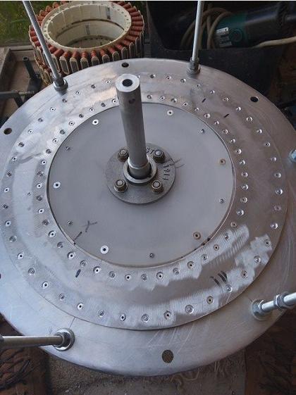
Fixed non magnetic alum conductor plate and 2 way central hub. The shaft is cut in the middle so 2 motors can spin the rotors in opposite directions.
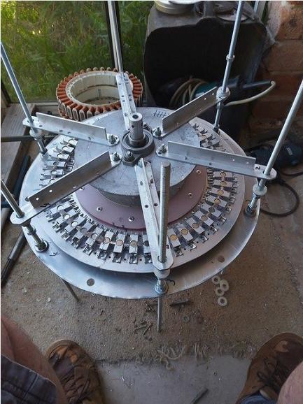
The washing machine stators shown are nothing to do with this machine.
Top rotor assembled and fitted. Motor drive shaft fits into hole at top of shaft. External brush motors are used, but there is room for axial BLDC motors to be fitted internally.
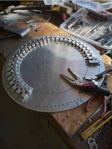

Assembling a rotor with a single row enhanced Halbach Array of 10mm x 10mm cylinder magnets N35. Enhanced means the Halbach Array is a 2 way arrangement.
The rotor diameter is 295mm to the center line of the Halbach Array. The circumference here is 927mm. At 1200 rpm the magnet array is moving at
18.5 meters per second.
This type of construction should be able to cope with 3600 rpm = 55 mps.
When facing a 3600 rpm counter rotating conductor the interaction would be at 110 mps.
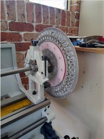
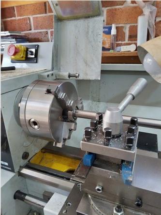
Balancing a rotor.

