
Possible Way To Fabricate A Casing For The Rotor
Magnets
Magnets

I have been using bicycle wheel rims as a casing for rotor magnets. These are circular, cheap, and readily available. But what is required is for the opening to be on the inside. An inside out bike rim. Centrifugal force would then keep the magnets inside the casing.
Machines to manufacture bike rims look very complicated and expensive. My solution would be to use 8 laminations of 0.6mm aluminum to form the casing. The joins would be staggered, so welding would not be required, and blind alum rivets would give extra strength.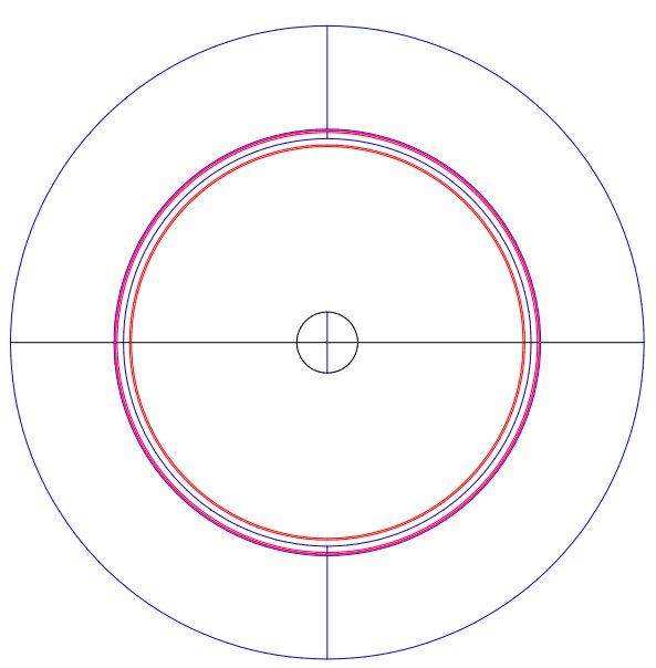
The Rotor is 650 mm diameter. The Magnets are 20 mm diameter x 10mm long, fitted into 25 mm dia x 3 mm bored out alum tube holders.
The Former dimensions can be altered to suit a smaller or larger rotor.
Positions have been marked on the plan drawings for a 64 poles 48 coils arrangement.
The Former Body is made from 2 rings of 32mm chipboard glued together. This assembly can be split into 2 sections (or perhaps 4) to allow the completed Rotor to be removed.
These diagrams use a 72 magnet poles, 54 coil positions configuration for the BLDC Motor.The Former dimensions can be altered to suit a smaller or larger rotor.
Positions have been marked on the plan drawings for a 64 poles 48 coils arrangement.

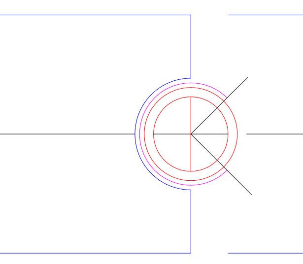
This enlarged image of the inside diameter of the former body shows 1 of 8 (suggested) sheet alum pieces (magenta). It spans around 75% of the minor diameter of the rotor. If a 30mm router bit is used there should be a gap of 5mm between the magnet holder and the wooden former body. If 0.6mm sheet is used, 8 layers would be required.
Perhaps the 1st layer could be left attached to the Former Body to prevent damage.
In this example the Magnet holders could be reduced to say 22mm, and a router cove bit of 25.4mm (1") used. This would allow 5 or 6 layers of sheet alum.
The 30mm cove bit would allow for bigger magnets, possibly up to 25mm diameter.
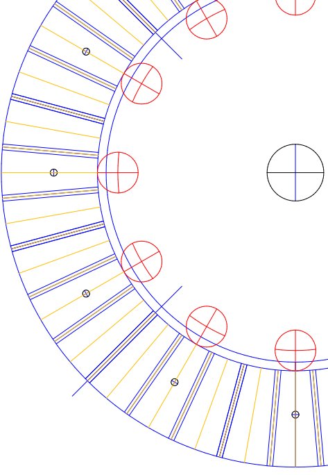
This shows how 12 Roller Formers could be arranged around the inside of the Former Body. The Formers need to be adjustable back towards the center about 40mm, and made to simultaneously move outward in very small increments to roll the annealed alum sheet into the required shape. One layer at at time.
There are 12 holes marked for mounting the Former Body.
There are 72 Pole position lines marked.
There are 36 10mm radial hole positions marked. These are to enable drilling 4.8mm holes and fitting of alum rivets into the completed Rotor Casing, from the inside, before the magnets are fitted. This should strengthen the Rotor Casing, before the Rotor is removed.
There are 4 positions marked where the Former Body could be dismantled.
It may be easier to make the Former Body rotate, and the extendable Roller assembly to be fixed. A Vee Belt groove could be routed around the Former Body to make a slow turning high torque machine, or a small diameter rubber wheel acting directly on the former body may be better.

The location of the 10mm rivet drilling access holes.
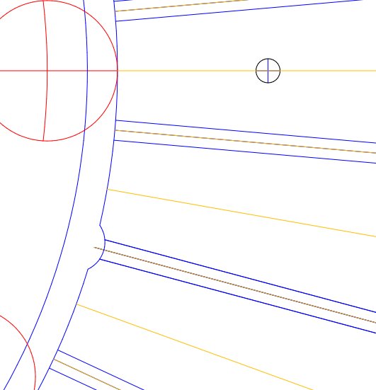
The inside of the 30mm groove would need to be set back about 3mm locally using a router coving bit, to accommodate the rivet heads.
Each layer of the casing would need to be hammered into this recess. When all layers are done the rivets can be fitted, while the former wheels are still in place.
The broken off steel mandrel stem can be punched out from the inside before the Magnets are fitted.
Steel anywhere may cause problems with the operation of the completed machine.
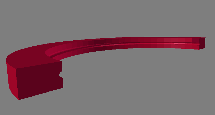
Two pieces similar to this, but without the groove, would be held together to make a full circle, and also able to be dismantled. The groove would be made by a router jig, attached to the main body, and rotating about the circle center. The jig should allow vertical movement to true up the main body, and horizontal movement to make the groove. This jig will only make one size rotor. Two layers of 32mm benchtop MDF or similar should be OK.


