

BH
CL
CL
BH
AL
AL
CH
AL
AL
CH
BL
BL
AH
BL
BL
AH
CL
CL
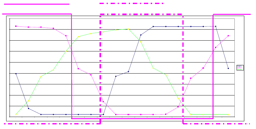
The lines are a bit shaky, but are the actual voltages read off the motor. The crossover points can be clearly seen, and switching voltages can be set at about 3v for the high side and 1v for the low side.
BL or BS

BH or BN
5v
0v
Another view of the same graph, with the output from OpAmp B added. The switching point reference voltages are adjustable, and these are easily set via 2 trimpots which simultaneously adjust all 3 OpAmps. When the Hall Sensor voltage on BH drops to (say) 3volts the BH output on OpAmpB changes instantly from 5v to 0v. The Hall Sensor voltage continues to drop and at 1volt the BL output on OpAmpB changes instantly from 0v to 5v.
A similar but offset pattern emerges when the other 2 Hall Sensor outputs are converted into this digital format. This 6 step pattern is identical to the 6 step switching required for the BLDC motor to run. The OpAmp outputs from the 3 Hall Sensors can therefore be used to directly power the mosfet drivers.
A similar but offset pattern emerges when the other 2 Hall Sensor outputs are converted into this digital format. This 6 step pattern is identical to the 6 step switching required for the BLDC motor to run. The OpAmp outputs from the 3 Hall Sensors can therefore be used to directly power the mosfet drivers.


