

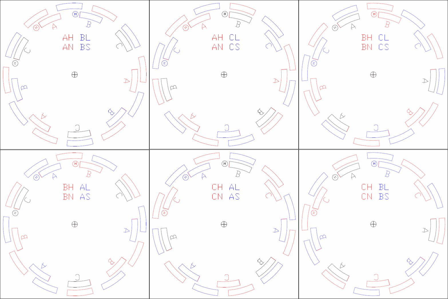

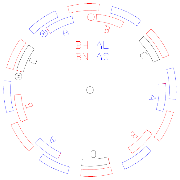
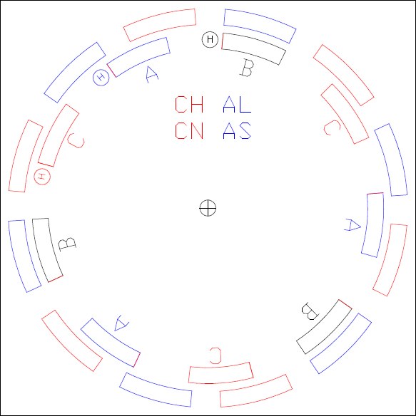
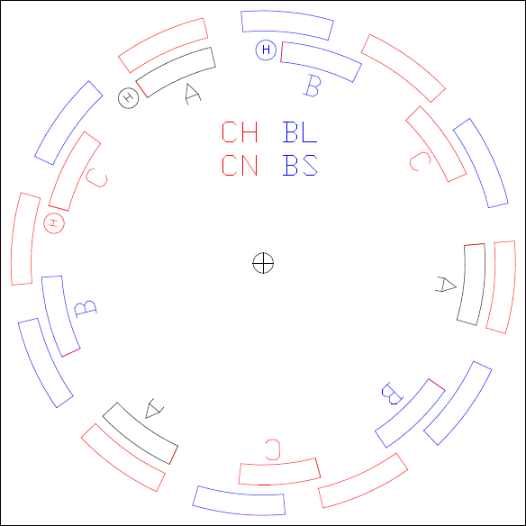
In this layout, the rotor is around the outside. It is a 12 magnet 9 coil motor. Six steps traverse 1 North Pole and 1 South Pole magnet. On this example that is 60deg travel or 10deg per step. The inner coils change color/polarity as they switch between steps. One coil remains off during each step and is colored black. Red is for North Pole, and blue represents South Pole. These motors are also called Stepper Motors. With computer control they can be forced to move in steps either forward or reverse. The degree of movement is the number of magnet pairs times 6. The example shown here has 6 magnet pairs x 6. Each step is therefore 10degrees and is shown stationary below.
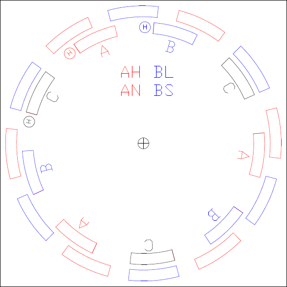
The like color poles are repelling each other, and the unlike are attracting each other. The red "A" North Pole coil is repelling the North Pole magnet, and simultaneously attracting the blue South Pole magnet. Meanwhile the blue "B" South Pole coil is repelling the same South pole magnet, and attracting the next North Pole magnet.
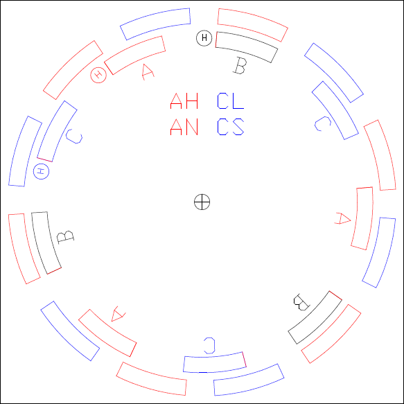
The 3 Hall Effect Sensors enable the switching circuit to "know" exactly where the rotor is positioned in relation to the motor's 6 steps. In the example above, the Hall Sensor near coil "C" detects that it is in the vicinity of a South Pole magnet and sends a signal to the decoder to turn on coil "C" to South Polarity. The Hall Sensor near coil "A" detects that it is in the vicinity of a North Pole magnet and sends a signal to the decoder to turn on coil "A" to North Polarity. The Hall Sensor near coil "B" detects a gap with no magnetic field, and sends a signal to ensure that coil "B" is turned off for that step. "AN CS" means "A North C South". "AH CL" is the same, but refers to 2 transistors, a High Side MOSFET "AH"which switches the positive supply to the motor, and a Low Side MOSFET "CL" which switches the motor to ground or negative. There are 6 MOSFETS, and they switch in the following sequence.
BL AH, AH CL, CL BH, BH AL, AL CH, CH BL
One MOSFET is not switched off each step to make the required transition.
BL AH, AH CL, CL BH, BH AL, AL CH, CH BL
One MOSFET is not switched off each step to make the required transition.
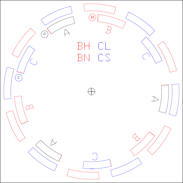
This last step simply loops back to the first step, and the motor will run continuously.


