

October 2014
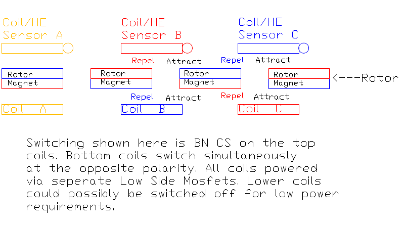
It may be possible to design an alternative to the 3 phase bridge switching of this BLDC motor. Instead of using 3 coils, with reversible polarity switching via a High Side and Low Side Mosfet bridge to control the 6 steps, use 6 coils, all switched on the Low Side.
Minimum requirements 6 coils and 8 magnets.
Pros
No floating HS Mosfet with associated driver and circuitry problems.
No changes to any control circuits except the Mosfet board.
Each coil has 50% less on time, so less heating.
Each Mosfet has 50% less on time, so less heating.
Ease of paralleling LSide Mosfets.
Ease of heatsinking.
No need for complicated dual bridges.
Can use existing coils, which seem to work well.
The space required for extra coils is available.
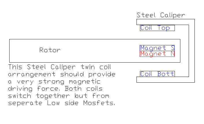
The motor power could be doubled by utilizing both poles of the drive magnets. This would require a steel caliper with coils mounted top and bottom. The drive magnets would need to be rotated 90 degrees. The magnetic flux path may possibly be greatly enhanced.
Critical timing of the Mosfets may not be required. The Dual Hall Effect Decoder may not be needed, just the single decoder. Power output may be enhanced by timing overlap, where 3 Mosfets will be turned on at any one time, with absolutely no possibility of Mosfet destruction.
It may also be possible to have no decoder for the hall signals. The signal may be able to directly operate the mosfet switching. The Hall signal would be inverted to operate the opposite polarity coil swithing.
When a coil switches off, the back EMF spike may create a small drag reduction assistance for the associated magnet as it moves away from the coil.
Cons
3 coils on and 3 off at any time. This may cause drag as there may be more generating than driving. This may not occur as the motor has a huge air gap. The electromagnets used to drive the motor are very powerful compared to to the strength of the moving ferrite magnets to act as a generator. The normal BLDC motor always has one coil dragging, or generating, and this does not appear to be a problem.
Requires the space and circuitry for 3 more coils, with no increase in power output.
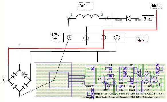
See below for proposed layout. This has been built for the Stabilizer Coils and is working well. The Mosfet has the center leg removed. It is bolted onto a short section of alum U section, together with the bridge rectifier. A small PCB attaches directly to the Mosfet legs via screw terminals. The 18v Mosfet gate is supplied from the Low Side only of an IR2101 driver. The 18v switching signal is supplied from a separate (tested) board with HCPL2200 Optocouplers. All the other connections are heavy cable to suit. This arrangement could be paralleled with up to at least 4 boards if required for a high current motor.

Electro--choke--electro
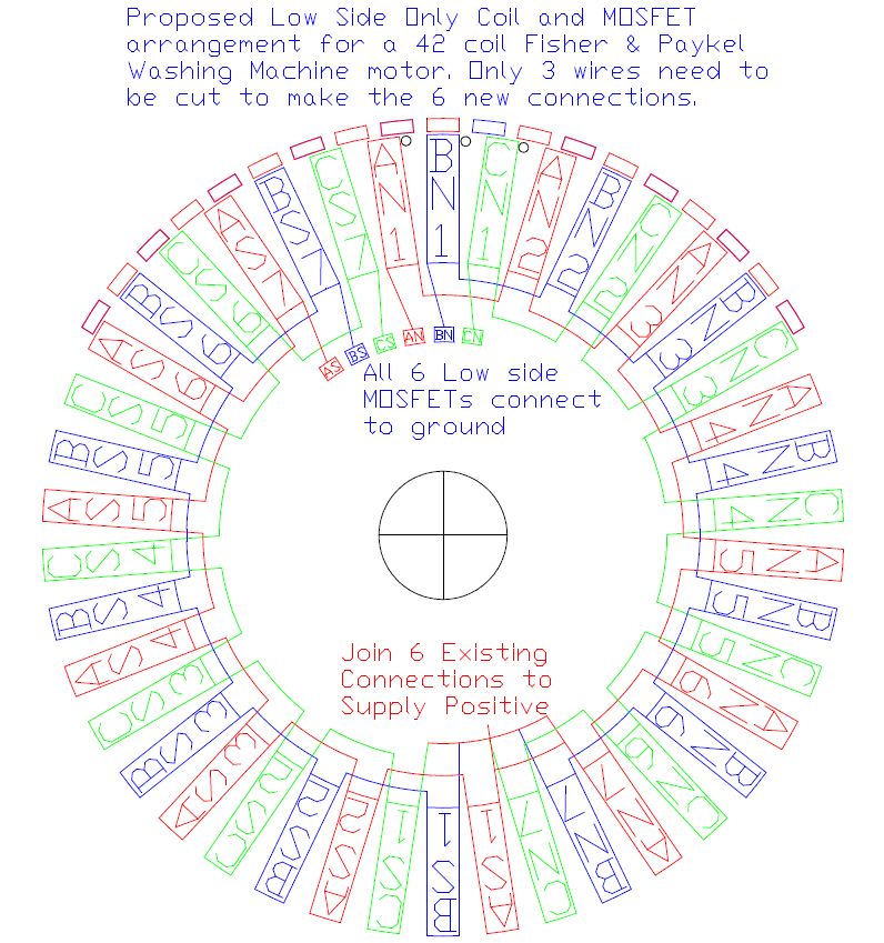
Below is a possible layout for a F&P Washing Machine motor. I have had limited success at getting this type of motor to run on 36 volts with the usual 3 phase bridge arrangement. No rewiring at all with this method. Just cut 3 wires and extend to the 6 MOSFET positions. The six coils created are automatically arranged with the correct polarities. With 36 volt supply the voltage to each individual coil is 5 volts. The F&P motor runs at about 10 volts per coil so this arrangement may need modifying by doubling the supply voltage or paralleling some or all of the seven individual coils.


The above setup should have double the number of coils. The minimum requirement to operate would be 6 coils at the top position. If a further 6 coils are fitted to the bottom position, and switched simultaneously with its opposing mate, there would be a doubling of power output. I suspect the flux path created with an upper/lower pair operating together should be a more efficient arrangement.


