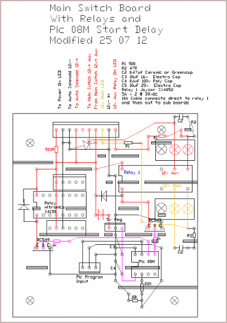


As there are 3 power supplies for this machine, the Main Switch is a small light duty switch which controls several relays.
The 36 volt motor supply utilizes a 30 amp car type SPDT relay. The 18 volt mosfet gate supply is tapped from the main battery bank, using a small 6v sealed LA battery, and the 12 volt auxiliary supply both pass through DPDT Relay 1 on Board 1.
The Main Switch is mounted on a panel with 4 LED indicators, which indicate if all circuits are active, also to indicate that all circuits are inactive when switched off, ensuring that a faulty relay is found quickly.
The relays on Board 1 are controlled by a Picaxe 08M. A short startup delay is provided to allow capacitors to charge, as the surge may damage meters. The Pic may also be used to control regenerative shutdown.
The rotor is a BLDC motor, and will automatically go into regenerative braking on shutdown, or accidental power loss. This is not a feature required for this machine. I have designed a system whereby the rotor will freewheel if power is lost completely, but can be pulsed between freewheeling /coasting, and regenerative braking, in a controlled manner.
This "failsafe" system also incorporates diodes to ensure that any partial loss of power through, perhaps, a blown fuse, will still allow regenerated current to flow back to the batteries.
Board 1


