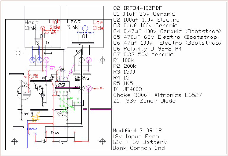


The Mk2 board was able to run the motor slowly but there were problems with
MOSFETS overheating. The IRF540PbF are rated at 28amps continuous, 100volts, 150 watts PD, but I was having trouble getting to 15amps.
Several changes have been made with the latest Mk3 board.
The MOSFETS are now IRFB4410ZPBF, 100v, 97amps, 230 watts PD.
The MOSFETS are being run with 2 in parallel so should have plenty of capacity,
and are now fitted in a lay flat position and held in place with screw terminals. This should help with troubleshooting as they can now be removed very quickly for testing or replacement. The power connection/heatsink bolt is attached directly to the PCB.


I have fitted a 6amp diode between the High Side source and the Low Side Drain. The HS MOSFETS were getting hot and this eliminates the problem. As this stops the freewheeling intrinsic diode from operating, another diode is fitted off the board to enable regenerated current to return to the battery, even if the 36v fuse beside the board blows. There is another fuse for the 18v on the PCB. Also on all boards are LEDs for visual confirmation of power to the area. These are Red for 36v, Orange for 18v, and Green for 12v Auxiliary. Four 10amp cables from each board are connected with a 4 way spade type automotive plug and socket. Another small 3 way plug supplies the signals for the MOSFET Driver. The board can now be installed or removed very quickly.
The OptoCouplers have ben moved to a separate board as they can run at least 4 IR2103 MOSFET drivers. I now have the capacity to run MOSFETS in parallel, or to run MOSFET bridges in parallel with some simple wiring changes.
The OptoCouplers have ben moved to a separate board as they can run at least 4 IR2103 MOSFET drivers. I now have the capacity to run MOSFETS in parallel, or to run MOSFET bridges in parallel with some simple wiring changes.


