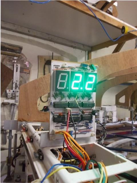

One tachometer is required for each Rotor, to monitor and control the rotational speed of the rotors. The second tacho will be required only if a second Rotor is installed. The first one has been built and operates satisfactorily. It uses a Picaxe 29X2 Micro as an I2C slave. The micro uses the "Count" command, to count pulses for 2 seconds from one of the Hall Effect sensor OpAmps on the Direct Drive PCB. The speed of the rotor is measured in Meters Per Second. The display is made from 3 x 1" Common Cathode 7 Segment LEDs. These are driven by 3 UDN2981 Darlington Source Drivers and decoded by 3 4511 BCD to 7 segment decoders. The Picaxe has a command "bintoascii" which uses the output of the "count" word variable and then puts the integers of the units, tens, hundreds, thousands, and ten thousands into 5 variables. Each of these is then sent as a binary code to the 4511 decoder. The thousand and ten thousand digits are included in the program, but not used in this application. The display has a decimal point permanently set on and the count is manipulated so the readout has a resolution of 0.2 MPS with a max reading of 99.8 MPS.
For my programming I prefer to use the BASIC language, and this is one of the main reasons for using the Picaxe system. In case there is a need to change to a non bootloader system, using the same chips as now, I have changed from the "bintoascii" command to using the "rem" remainder function. This is compatible with the two BASIC systems I am considering, Great Cow Basic (free) and PicBasic Pro 3 (paid), and appears to compile ok on both, and works on the Picaxe. Apr2016.
The micro outputs 8 codes using 3 output pins. These codes are utilized by the guide wheels and stabilizers at startup and shutdown, and the rotor speed control and emergency overspeed shutdown. The codes sent represent ranges of values. All this is handled by a 40 pin Picaxe for each Rotor. This has been changed to sending the actual value via I2C serial and is converted to codes where required. Apr2016.
At present (Sep 2015) the system is set to start and run up to maximum speed. I see a
need to have each Rotor reach Idling Speed, and when both Rotors are Idling then a manual switch will allow both Rotors to go to Running speed simultaneously, with neither allowed to be more than 5% from the other. Incorporated into this arrangement is a means of adjusting the max rotor speed temporarily while each Rotor is at Running speed.

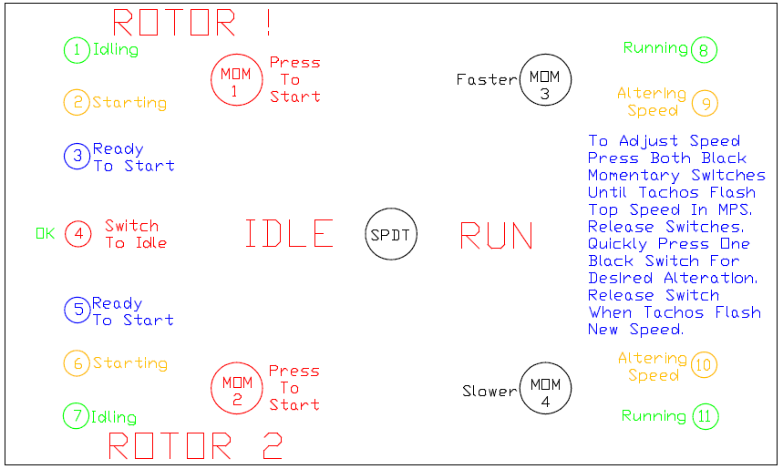
Panel setout for Startup, Idle to Running, Running to Idle, and Rotor speed adjustment.
This will require another 40 pin Picaxe to communicate with the two tacho Pics.
The proposed operation is designed to enable speed adjustment when only 1 Rotor exists, with only minor alterations for dual Rotors. The speed adjustment is to enable safe incremental testing of the Rotor. The Program will allow say 3 MPS increase in 0.2 MPS jumps without shutting the Rotor down. The Program would then be altered to the new max speed.
The proposed operation is designed to enable speed adjustment when only 1 Rotor exists, with only minor alterations for dual Rotors. The speed adjustment is to enable safe incremental testing of the Rotor. The Program will allow say 3 MPS increase in 0.2 MPS jumps without shutting the Rotor down. The Program would then be altered to the new max speed.
Startup Conditions
Main Switch activates 12v Aux initially which turns on 8 Pin Startup Pic. This then powers all Power Supply Relays and the Start / Run Micro.
Switch SPDT must be set to Idle. BILED4 will be ON GREEN, or BILED4 will be ON RED until switch set correctly.Main Switch activates 12v Aux initially which turns on 8 Pin Startup Pic. This then powers all Power Supply Relays and the Start / Run Micro.
If LED4 is GREEN and all Guide Wheels are in the correct position then LED3 BLUE will FLASH.
Rotor1 can now be started.
Press MOM1 switch. This will activate a relay which feeds power to all 12v aux circuits for Rotor1 and sets the startup guide wheels and stabilizing systems sequence in action and will then automatically start Rotor1 if everything OK.
When Rotor1 is powered LED3 BLUE will turn OFF and LED2 ORANGE will FLASH until Rotor1 reaches IDLE speed.
When Rotor1 is at IDLE speed LED2 ORANGE turns OFF and LED1 GREEN turns ON to show that the Rotor is at Idle speed.
LED5 BLUE will now FLASH to indicate that Rotor2 can be started.
Press MOM2 switch. This will activate a relay which feeds power to all 12v aux circuits for Rotor 2 and sets the startup guide wheels and stabilizing systems sequence in action and will then automatically start Rotor2 if everything OK.
When Rotor2 is powered LED5 BLUE will turn OFF and LED6 ORANGE will FLASH until Rotor2 reaches IDLE speed.
When Rotor2 is at IDLE speed LED6 ORANGE turns OFF and LED7 GREEN turns ON.
Only when both GREEN LED1 & LED7 are ON can switch SPDT be set to RUN.
As Rotor1 & Rotor2 accelerate above IDLE speed both GREEN LED1 & LED7 turn OFF
and ORANGE LED9 & LED10 FLASH until RUN speed is reached.
At RUN speed both ORANGE LED9 & LED10 turn OFF and GREEN LED8 & LED11 turn on.
Switching to from Run to IDLE can only be done when both GREEN LED1 & LED7 are on.
Acceleration from IDLE to RUN and RUN to IDLE must have no significant difference between Rotor speeds, and must be automatically controlled if variation occurs.
Apr2016. The above panel has now been built and tested but only for one Rotor, and has the ability to gradually increase the speed for testing. Also a sequence has been incorporated for shutdown before Idle Speed by pressing both Mom1 & 2 simultaneously.
I2C has been installed. The panel has its own slave Pic, and there is now a Master Pic, both 40X2 Picaxe.
I2C has been installed. The panel has its own slave Pic, and there is now a Master Pic, both 40X2 Picaxe.


