Rotor Electronic Drive System
Test & Measuring Equipment
Test & Measuring Equipment

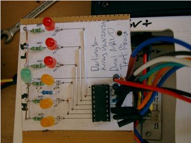
The small board with 7 LEDs is to check and adjust the motor timing low voltage control section. The 6 steps for switching are marked on the rotor, and as the rotor is moved a pair of lights will illuminate for each step. 1 orange for High Side and 1 red for Low Side. The green is to show the PWM voltage/current level.
This board has its own plug and can be removed or remain in place when the motor is running. It plugs into the Direct Drive Decoder PCB.
This board has its own plug and can be removed or remain in place when the motor is running. It plugs into the Direct Drive Decoder PCB.

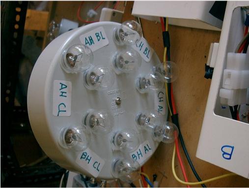
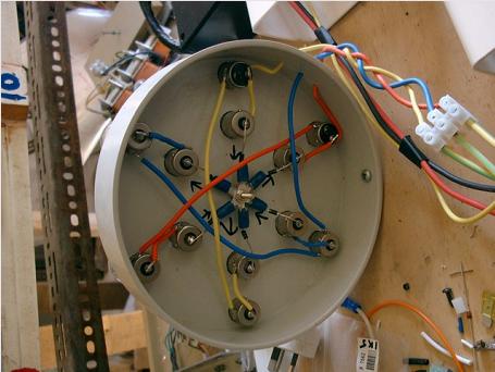
The lower pics are of a set of 12v car globes to test the high voltage motor timing. This is installed in place of the drive electromagnets, and also checks the motor steps. Four globes illuminate for each step.


