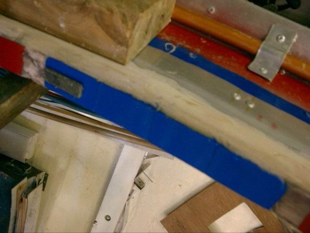


The original magnets used to drive this machine were 30 x 10 x 3mm as shown on the blue magnet. There were 168 of these, requiring 504 coil switchings per rev. I have run the machine slowly under its own power using these magnets, but decided to change them for the following reasons.
1 Difficult to obtain.
2 Switching rate may present problems with attaining maximum speed.
3 Air gap of 3mm between coils and magnets may be too restrictive.
4 As the coil is also 10mm wide, any vertical lifting of the rotor would move it away from the coils.
1 Difficult to obtain.
2 Switching rate may present problems with attaining maximum speed.
3 Air gap of 3mm between coils and magnets may be too restrictive.
4 As the coil is also 10mm wide, any vertical lifting of the rotor would move it away from the coils.
The new magnets are easily obtained and reasonably priced ferrites. There are four in each set, with the same polarity at the face. This layout also takes advantage of the exponential nature of locating magnets side by side. They are 40 x 25 x 10mm. 4 magnets gives 16 times the lifting power of 1 magnet. There are 36 magnet sets, 18 north pole, 18 south pole. With 6 switchings required for every magnet pair, the switching will now be 108 per rev. The magnets were fitted using the radius arm device I made for the small magnets, with only minor modifications. As these are much larger I used 3M Auto Body filler with chopped glass strands to attach them.
The coil layout I have chosen and tested off the rotor is 4 x 30mm wide coils connect together in series. I assume the exponential nature of the layout applies also to electromagnets as the power of this combination
is very strong. It repels as far away as 20mm. 10 to 12mm air gap when fitted to the rotor may be quite practicable. The Hall Effect sensors will also require a large clearance, and I have found that the sensitivity can be increased enormously simply by fitting a tiny ferrite bead behind the sensor.
