
Machine Frame or Stator
Assembling Radial Magnet Holder
Assembling Radial Magnet Holder
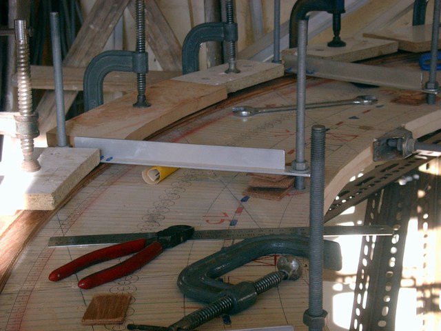
Pieces of plywood cut to a pattern are set out around the table. the joints must be staggered. First 2 wide layers, then 2 narrow layers to make the rebate.
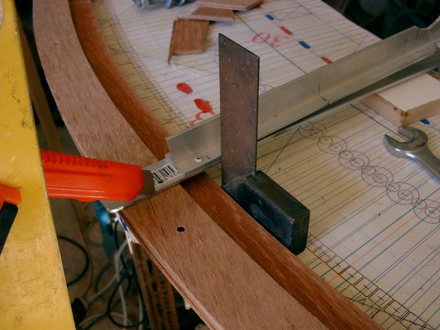
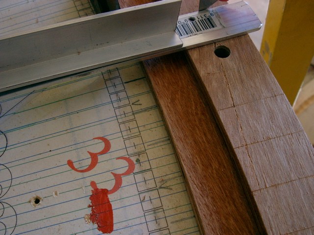
The magnet positions are marked out from the color coded lines on the table patterns.
The tee section straight edge is attached to the center pivot. A square is used to get the correct alignment.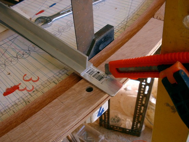
The lines are marked right across to make drill alignment easier. This is the 4th layer.
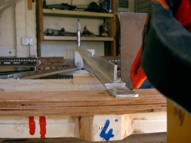
The threaded rod is removed to mark out and then replaced. They will also be removed and replaced one at a time temporarily for drilling.
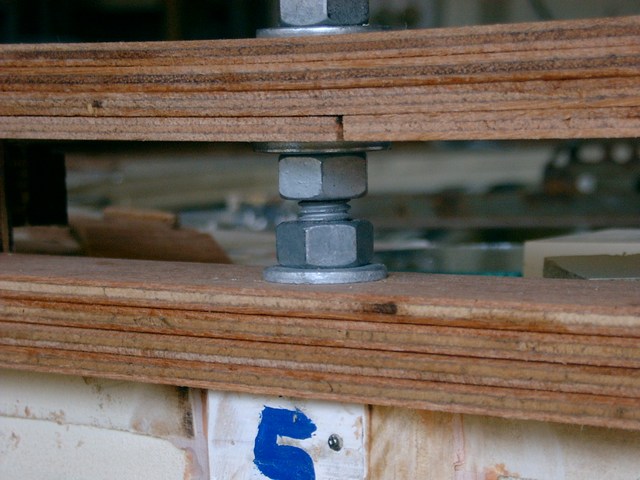
The next layer of narrow pieces is laid on top of the marked lines and not glued. The other layer are laid out and glued in place. When the glue is set the top section is lifted off, nuts and washers installed and the top section replaced at the correct height for the installation and gluing of a curved mounting for the magnets.


