Machine Frame or Stator
Guide Wheels Circuits
24 Volt Motor Reversing
Guide Wheels Circuits
24 Volt Motor Reversing

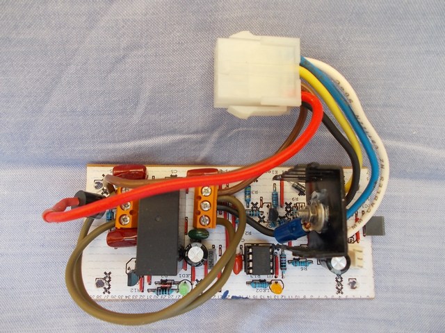
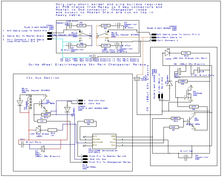
This board enables switching and reversing of the guide wheel motor where 24 volt motors are used. The yellow cable is the 12v or 18v supply to the mosfet gate. Six of these boards are required for the Retraction System. Isolated section: Relay coil is powered by 12v Aux which is controlled with 5v Aux from the micro. Another micro connection to the OptoCoupler controls Mosfet 18v gate.
This board can be used for 12 volt motors also. This is done by looping from the Red cable around to where the Yellow cable connects. It just needs to leave out capacitor C9, and change the Orange LED to Blue. Only 4 power cables instead of 5.
The boards I am using are almost the same, but are made for 12 volt motors only
and can be found here.
Guide Wheels Changeover Relay.sch


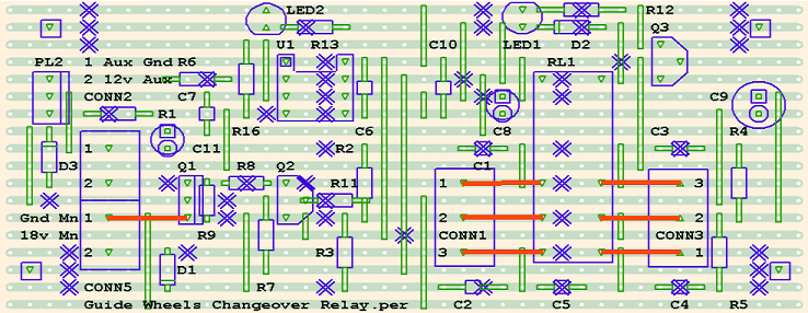
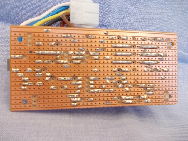
The DesignSpark schematic is used to create this VeeCad PCB layout. Actual size is about 107 x 48mm. Around the relay contacts are snubber circuits of 0.47uf greencaps and 47R resistors. The relays do not like DC and tend to melt the contacts if these components are not used. They have now been fitted to most of the relays on the machine.
The relay here is used as a changeover switch, to reverse the flow of DC, and therefore the direction of the motor. The actual power switching is done with the IRF540 mosfets. To take more current the PCBs should to beefed up on the tracks where shown in Red. This mosfet is probably overkill. The exposed brown looped cables are the changeover arrangement.


