

6
5
7
3
8
2
1
1 Frame mounting threaded rod.
2 Setup adjustment pin.
3 Adjustable postion axle .
4 Slew Ring Wheels.
5 Retractable Guide Wheels.
6 Repositioned drive magnets and coils.
7 Rotor.
8 Alignment and spacing bolt.
2 Setup adjustment pin.
3 Adjustable postion axle .
4 Slew Ring Wheels.
5 Retractable Guide Wheels.
6 Repositioned drive magnets and coils.
7 Rotor.
8 Alignment and spacing bolt.
4
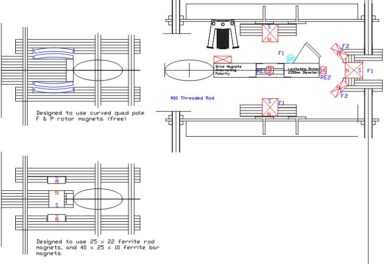
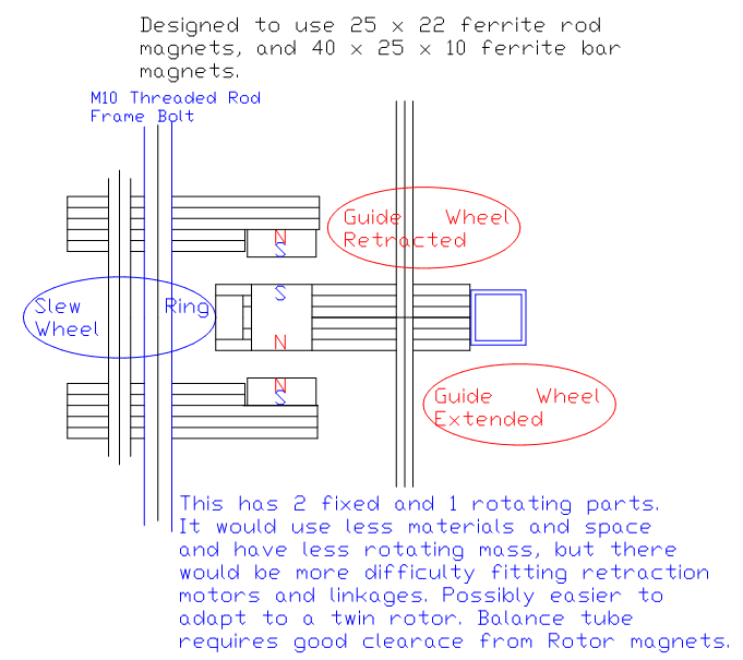
The above design is similar to the Spoke Wheel but does not use much internal space. The Guide Wheels are held firmly against the driven Rotor. When retraction occurs all components are rotating at the same speed. A smoother, more controlled retraction and Rotor levitation should be possible Repelling magnets are used to minimize friction vertically. Fixed Slew Ring Wheels (the same type of rollerblade wheels as used elsewhere) are fitted around an accurately ground circular track.
With minimal clearance, individual wheel adjustment, and some lubrication, friction should not be too much of a problem. The Slew Ring only needs to achieve sufficient speed for Guide Wheel operation.
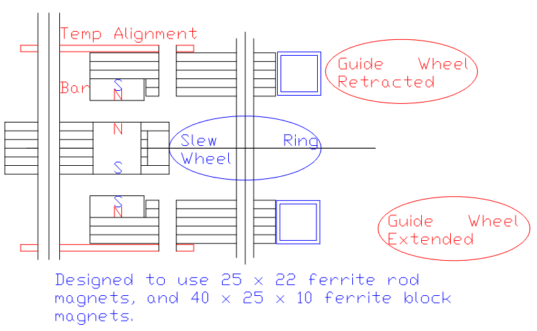
As with the Spoke Wheel design, it should be possible to mount retracting Guide Wheels on both top and bottom of the Slew Ring. This would enable 2 Rotors to be started / stopped with one component.

The above design has much less weight for the vertical magnetic bearings to support. Grinding the inside circumference face may be difficult. Steel balance tube probably required, but should be kept back from the Rotor's magnetic field. Probably impossible to keep a perfectly circular track over time.

Above is a compact version of the two rotating parts Slew Ring. To grind the circular track the access is easier, and the frame threaded rod holds it in place exactly where required over time. Two steel Balance Rings would provide better dynamic balancing as components change position during Startup or Stopping of the Rotor.

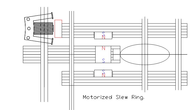
Motorized Slew Ring. This should enable the whole Slew Ring/Rotor assembly to reach a higher release speed more reliably. A smaller air gap can be used so the power would be greater than with the Rotor drive alone. It should also be easier to control Guide Wheel extension for Rotor stopping. This could be adapted easily to motorize both top and bottom sections. For the 3000 Machine this would allow 18 coils between Frame threaded rods, but if things are redesigned a little so that the coils are in front of the Frame rods then more coils could be installed for more starting power. The levitation magnets or bearing could have less bar magnets at the bottom. If only half are installed some compensation can be made for gravity, and the components should then be more equally repelled.


