Experimental Small Induction Machines
Levitating and Non Levitating Rotors
Levitating and Non Levitating Rotors
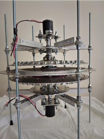
There are many ways that the rotors could be arranged to make the machine work. I have built 2 prototypes so far with no sucsess. A levitating rotor has always been a priority, until seeing the Graviflyer machine on Youtube. Where shafts and bearings are used I incorporate as much insulation as possible.Some of the possibilities are listed below.

single row enhanced Halbach Array attached to each.
A fixed non magnetic conductor plate between
A fixed non magnetic conductor plate between
rotors. This build is 300mm to the centerline of the
Halbach Array.
Halbach Array.
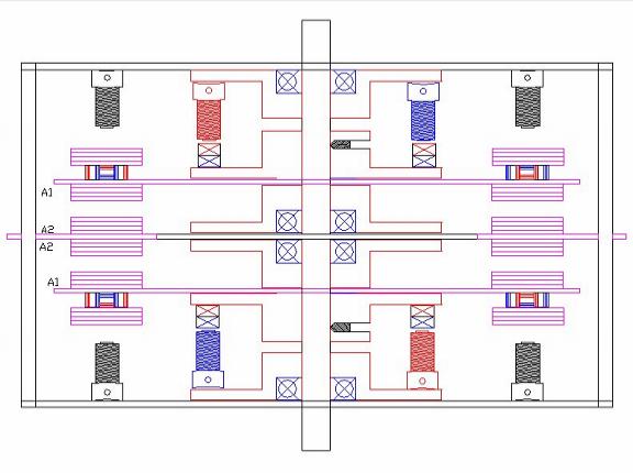
A concept drawing shows A2 as the fixed non magnetic conductor plate. A1 are the 2 counter rotating rotors. Attached to the rear of the Halbach Arrays is another conductor plate. The adjacent Black electro magnet coils would interact with the rotating conductor to provide additional acceleration. The Blue and Red coils and magnets are the BLDC drive motors.

Layout 2
2 rotors, counter rotating. I rotor has the magnets, and the other rotor is just Alum plate.
2 rotors, counter rotating. I rotor has the magnets, and the other rotor is just Alum plate.

Layout 3
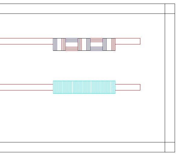
2 rotors, counter rotating. Each rotor contains both magnets and conductor plate. This
arrangement may have the benefit of a better rate of change of magnetic flux, because of the
alternating magnetic fields. It should also be double the DGF strength of Layout 2. It should
also be more equally balanced.

Layout 4
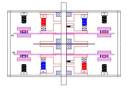
Magnetic Gears. This could apply to any of the 2 rotor designs. It may be possible to arrange
the magnetic gear magnet pairs to also use the magnets for the BLDC motor. This is gearing,
so the rotors could never spin at the same speed. A motor / rotor using 8 magnet pairs could
be coupled with a counter rotating rotor fitted with 9 magnet pairs for a ratio of 8:9. For
counter rotation the formula is to add total magnets, and divide by 2 for intermediate flux path
components. 16 magnets + 18 magnets = 34 magnets / 2 = 17 steel bolts or ferrite bars.

Layout 5
This is a torroidal or ring rotor composed of alternating polarity magnets fully enclosed within a non magnetic conducting metal torroidal shaped stator. The magnets are used for both rotating as a BLDC motor, and levitating the rotor by induction. Each magnet is made from 2 cylindrical magnets forced together with like poles facing, and locked into a strong housing. This creates a magnet with a very strong field radiating from the center, with the end poles remaining at about their original strength. Each end has the same polarity.
If two of these magnets are made with the polarities reversed, then these magnets will have opposite polarity at their ends, and so will be attracted to each other. When joined in this way the field at the joint disappears and may enhance the center field.
These magnets appear quite suitable to operate as a brushless dc motor. The coils required would be wound around the outer torus diameter.
This machine layout is based loosely on the Inductrac Train which uses Halbach Arrays travelling over non magnetic conductors. As the lift increases the drag decreases. The Inductrac reaches a point of equilibrium naturally, but cannot rise to a point where the magnetic field leaves the track.
My design has the train as a loop or rotor, enclosed within a non magnetic tunnel or stator. The radial magnetic fields will move through the entire tunnel. The rotor will rise off the wheels and at some speed will centralize in the tunnel. To create the right conditions both the tunnel dimensions and the magnets must be matched, and this can only be by trial and error.
There are 36 magnet poles, made from 72 22mm D x 25mm L ferrite magnets. These are fitted around a non magnetic bicycle rim. The diameter at magnet centers is 650mm.
The tunnel or torus is made from Alum tube 76mm OD x 4.5mm wall thickness. This is cut into 27 sections @ 13.33 degrees to create a circle. Each section is then cut in half so an entire lower section of the torus can be welded. This has 3 small wheels, onto which the rotor sits.
The upper half torus can be partially fabricated, but some areas need to be fitted as inspection covers.
The coils are then wound around the 76mm Diam tube.


