
Experimental Levitating Rotor Machines
Construction Photos
Construction Photos
A Magnetic Levitating Torus Rotor
Within A Non Magnetic Metal Torus
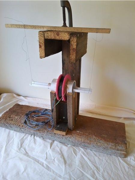
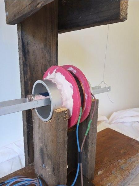
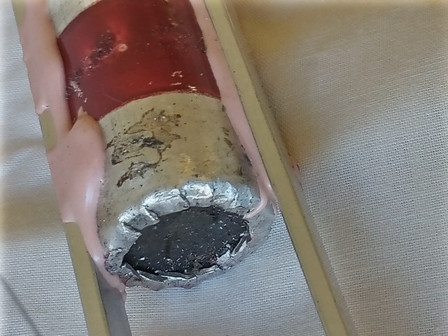
The test rig was powered with 36v DC controlled with PWM. Very little power was required to move the rotor. The coil is about 600 turns of 0.5mm copper. I used reclaimed wire from Fisher & Paykel washing machine motors. The coil is about 20mm wide.
The magnetic field from the magnets extends into and through the tube walls. Hall Effect sensor readings on the outside of the tube wall show a moderate field strength, which then reduces to zero at about 10 mm from the wall.
To get reliable Hall Effect readings on the tube exterior for the motor drive timing, a small ferrite bead mounted behind the sensor will give an increase in field strength of about 10%.
The sensors could be mounted internally. The sensors should be mounted on the inner diameter of the torus where there would be less interference from flux leakage where the magnets are angled.
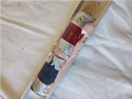
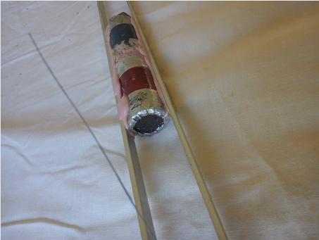
The 22mm diam magnets are retained in alum tube 25mm x 1mm with ends cut and bent as shown. Construction adhesive also holds them securely in place within the tube.
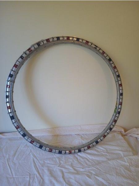
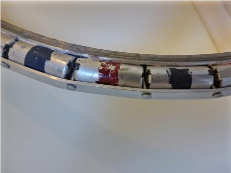
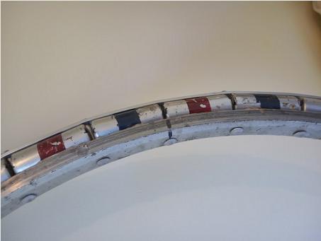
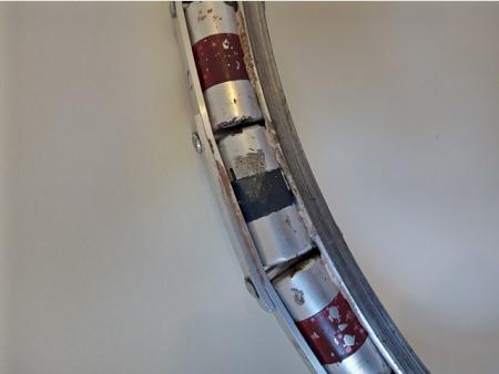
Alum flat bar 12mm x 3mm and alum rivets hold the magnets firmly in place on the rim. They are also bedded on epoxy. The rotor weighs about 6Kg. Some more epoxy is needed on one side to make a smooth surface to run on the wheels.


