Experimental Levitating Rotor Machines
Construction Details
Construction Details
A Magnetic Levitating Torus Rotor
Within A Non Magnetic Metal Torus
Rotor No 4 Stator No 2 Construction Details
Not Yet Built Mar 2025
Not Yet Built Mar 2025


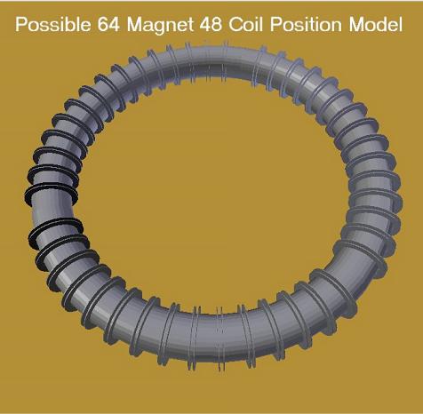
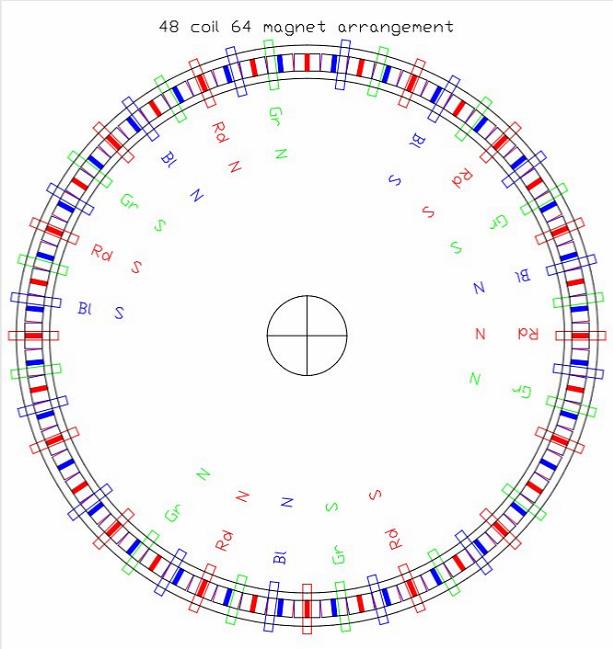
Possible layout for a Torus Machine with 48 coil positions and 64 alternating magnet poles. Three coil positions are left vacant at 120 degrees apart. This creates perfect spacing for 3 wheels, and also the correct phase positions for each of the 3 Hall sensors. This torus stator would have 48 lobsterback sections, but only 45 actual coils.

The 3 missing coil positions are perfect for Hall Sensors and wheels location. The drive coils have an unused coil position between them to eliminate any possible interference. The groups of drive coils are not able to be correctly spaced at 120 degrees, but should be OK.
The 27 remaining coils can be used in shorted coil experiments for increasing the chance of rotor levitation.The 64 radial field "supermagnets" are shown. Each "supermagnet" is made from 2 magnets retained with like poles facing.

The dimensions of this machine have not been finalized. They will probably be similar to the first machine, about 650mm diameter to the centerline of the rotor.
The rotor may use 18mm diameter neo magnets, or perhaps 20mm.The inner diameter of the alum tube may be 57mm. There is a tube size 63.5mm od x 3.25mm wall thickness.
A better choice may be 60mm od x 3mm wall = 54mm. A centrally located 18 mm rotor would give a clearance of 18mm between magnet and tube.
Required clearance is just guesswork and experiment.


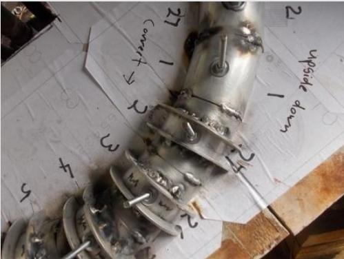
This is Torus stator No1. The coil wall pieces were added after the lobsterback sections were welded together. It was only just possible.There are 27 coils.
The No 2 stator will have the coil wall pieces welded onto the individual lobsterback sections first, then the entire assembly will be welded together. This will allow much closer coils. There are 48 coil positions, but 45 actual coils, or nearly 90 coils if the space between coils is utilized.
Stator No1 is made with 4.5mm wall alum tube. No 2 stator will be 3mm wall tube. The coil wall pieces are 3mm thick, so the welding should be easier with similar thickness material. More switchable shorted coils should compensate for the reduced wall thickness.

There will be no webbing pieces fitted. This will allow winding of more coils between the main coils. The webbing was difficult and useless.
The coil windings should be sufficient to hold the two halves together, but some mechanical fastening would be better.
The coil windings should be sufficient to hold the two halves together, but some mechanical fastening would be better.

No 4 Rotor will be built when I can make a machine to construct a layered sheet alum structure similar to an inside out bicycle rim.

