Rotor Electronic Drive System
Picaxe Microprocessor
Picaxe Microprocessor
For the most part, the machine uses Picaxe 18M2 micros. I have found that it is easier to use a small stand alone board which has been found to work correctly, rather than try to integrate the micro into each new PCB design. The connections are by way of small header plugs. A 2 way for the 12v supply, a 3 way for the programming, a 10 way and a 12 way for the various inputs and outputs. Listed in the Jaycar catalouge, the10 way is HM3410 & HM3420. The machine has a 10amp 12v isolated auxillary supply for the micros and relays, so each board has a 5v regulator. A green LED is fitted to enable quick fault finding around the machine. The main power supply has red LEDs to indicate 36v and orange LEDs to indicate 18v.

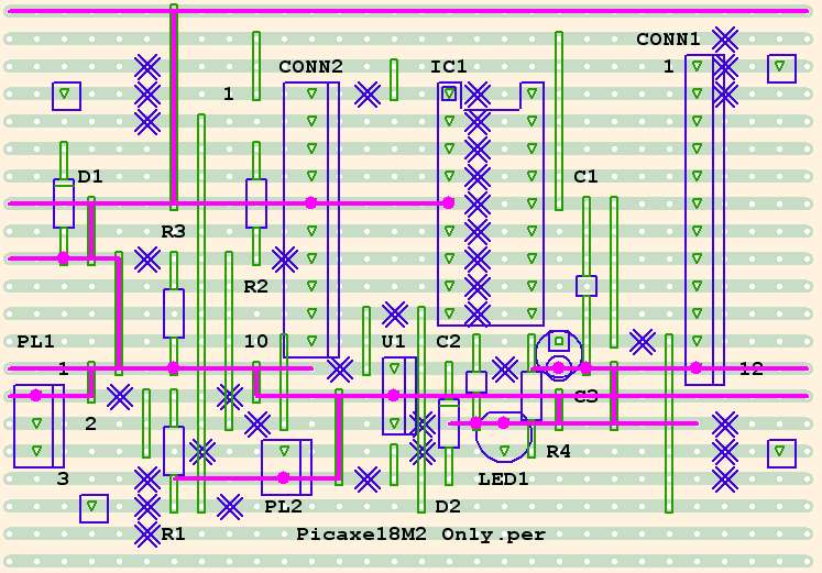
VeeCad Circuit @ about 200%

This board shows the ground tracks and connections in pink. Any micro pins set as input may require a resistor of 100k to ground, to ensure a definite zero. An extra link has been added so any pin/s can have this resistor fitted. The resistors are not shown, and are normally not required, but the layout of my machine means there are some very long cable runs, with possible stray voltages and false triggering. The resistors are not required for ADC input.
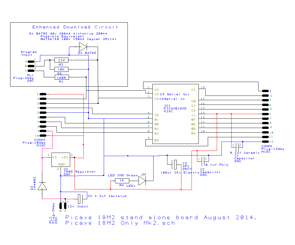
DesignSpark Circuit

The Picaxe Enhanced Circuit extra components have been retained, although the Picaxe Manual states they are no longer required if using the Picaxe USB download cable.
I tend to use older computers with serial ports in the workshop. Also I use I2C in some areas and this may work better with the Enhanced Circuit. Only 2 extra components are required.

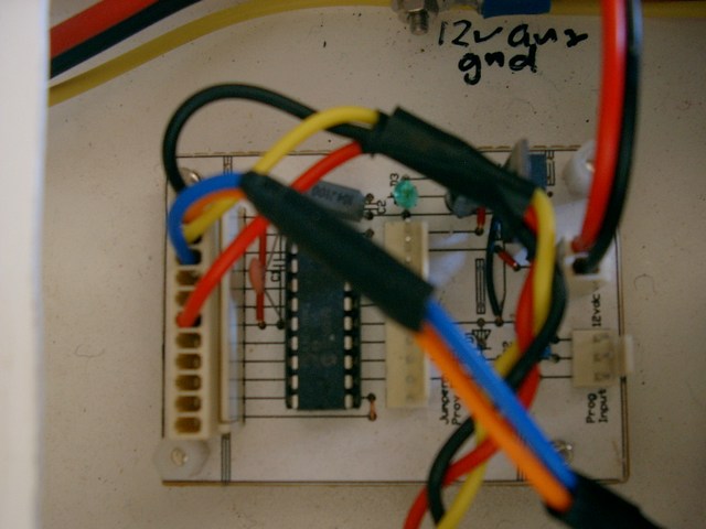
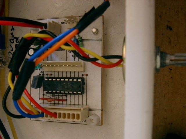
These pics are of my first board using a cad program.


