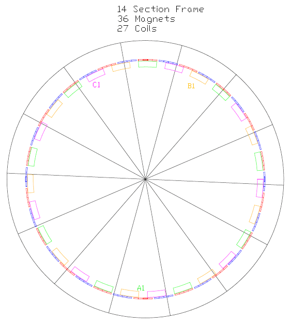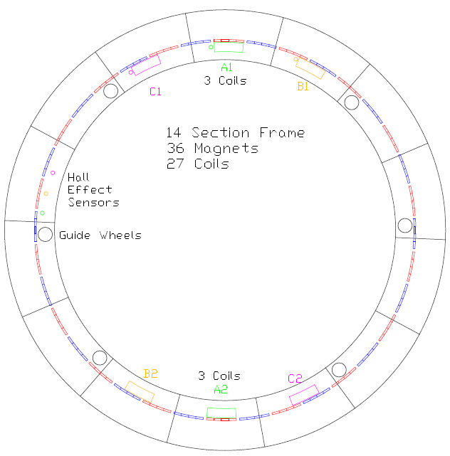

The frame for the machine is in 14 segments. The Mk1 coils were set out in seven sets around the frame. To make the changes to the 3 160mm long, multi part coil system means that the coils are fitted anywhere they will go. They are unevenly spread around the machine, so it is amazing that it runs at all. Ideally the coils should be an equal number. 6 coils should be fitted, with each phase directly opposite so that the rotor's levitational stability chances are maximized. My coils are in a 27 coil system and can be forced into the correct alignment. With the magnets being in pairs with alternating polarities around the rotor, the matching polarity is always directly opposite. While the 14 section frame seems problematical, the lower drawing shows it to be quite practical.

The picture below shows the layout of the 3 coils being used. A1 was put at the bottom to allow for 7 equally spaced guide wheels around the machine. All other coil positions are not used.

By reducing the guide wheel count to 6 the coil layout below can be achieved. The wheels are easily moved, and the sensors remain in the same position. Some of the wiring to A1 may need shortening. The extra power to the motor may be more helpful for getting the rotor to stabilize quickly. Actual running current is not likely to increase.

The top drawing shows all possible coil positions with the phases color coded. The lower drawing shows 6 of the coils in opposing sets of 3. The 2nd set of coils have been repositioned directly opposite their counterparts, which is only possible with an even number of frame sections. This will give a balanced application of power to the rotor. In fact, as of Dec 2012, I have been running the machine using just 1 set of coils on one side, and it seems to work OK. This was done to reduce the cable length between coils as long runs were creating voltage spikes which were transmitting into the control circuit. The common connection to the 3 coils is now kept short and isolated from all other wiring, and the coils have been fitted with non polarized electrolytic capacitors. I may need to complete the 2 coil sets arrangement to enable a quicker startup for rotor stabilization, but it appears that it may be possible to switch one set off when running. The MOSFET bridges required for the second set of coils would be mounted close to their coils. These can be driven from the same system as used by the first coil sets.
The Hall Effect sensors would normally be located close to one side of a coil, but they can be mounted close together within another spare frame section. Their order is scrambled but this has no effect once they are correctly connected. This way the sensors can be mounted together as one unit.
The Hall Effect sensors would normally be located close to one side of a coil, but they can be mounted close together within another spare frame section. Their order is scrambled but this has no effect once they are correctly connected. This way the sensors can be mounted together as one unit.
As at Feb 2017 the 2nd set of 3 coils has been mounted by extending the high voltage cables and forcing the mosfets to carry double the current. This works but still the motor is not powerful enough to rotate at a speed suitable for Guide Wheel retraction. The whole Guide Wheel setup has now been changed. A central Spoke Wheel has been built and installed and connected temporarily to the Rotor. The existing motorized Guide Wheels have been removed, but will be fitted to the Spoke Wheel later when the motorized Rotor can be tested to a suitable speed. Another set of 6 coils has been fitted, using a Low Side only switching arrangement. The Spoke Wheel has considerable air friction, but testing so far has achieved 7 MPS or 1 RPS or 60 RPM. More power can be applied by motorizing the Spoke Wheel and this is currently being done.


