
Dec 2014
Attempts to stabilize the rotor using Guide Wheels alone have not proved successful so far.
Full levitational stability of the rotor should be possible using electromagnets. The guide wheels would then be of secondary importance, just used for initial alignment.
I have fitted 45deg angled ferrite magnets (40x25x10) around the frame or stator. These are attached on each alternate frame section, with top and bottom also alternating. The stability improvement with this arrangement is quite dramatic, but not enough to overcome
Earnshaw's Theorem.
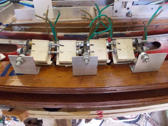
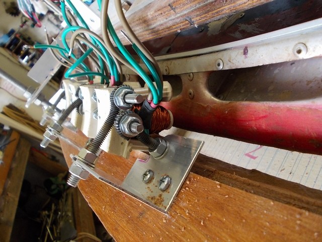
I am constructing some 4 part coils made up of sections of F&P Smartdrive stators, similar to those used for the Drive coils. These will be also fitted at a 45deg angle, in the vacant spaces on the frame. Initially 7 on the top, but allowance made for 7 underneath.
There is much info about using Hall or Light sensors and micros to hold a falling object in midair. While I will probably need to use one of these methods, I intend to try just pulsing the rotor. The steel cores of the coils have a very strong attraction to the rotor magnets in the 45deg alignment position, and very strong repusion when powered. The 7 top coils should lift the rotor a small distance when unpowered, and then drop the rotor when powered to repel. This would be repeated at a rate to be determined by experiment. The 45deg alignment also means that any movement should be in a centralizing or cone shaped direction . If the top coils alone cannot do the job, then a set of 7 coils will be fitted below. These would pulse out of phase with the top set. The 40 pin Picaxe micro I am using for Rotor control has 2 independent PWM timers, and I will use one of these to supply the pot adjustable 15.6k voltage control. The PWM frequency must be the same for both PWM channels but the dutycycle can be different. This makes using the 2nd PWM pin of no use for this application as I require a very slow pulse. The solution is to use some spare capacity on a nearby 18 pin Picaxe 18M2+ to create the slow pulse. This pic allows parallel tasks, and is perfect for this job. It currently waits for a changed input, and then changes some outputs. Its new task uses normal high / low commands to enable very slow operation, and a ramp has been programmed.
Initially the program has been set to a freq of 5. Each period then has an adjustable dutycycle of a percentage, currently 42/58 %. The period at the start is 200ms with 84ms on and 116ms off. A ramp reduces the period to about 20ms over around 30sec, retaining the original % profile. I have built a PCB to combine the signals from both pics through an AND gate for the top coils, and the slow signal for the lower coils passes through an inverter and then the AND gate. This allow the lower coils to pulse out of phase with the upper coils and to do so with the % adjustment giving the lower coils a longer power on time to compensate for the effect of gravity on the Rotor. Everything is easily adjustable in the program.
My reasoning for trying this is that the sensor system used normally to levitate a small object or magnet could also be adapted to record the data about the voltages and pulse rates required to levitate the object, and then this data could perhaps be used to operate a mass produced machine, using no sensors. I will attempt to guess the switching rates.
My Rotor is a somewhat different arrangement. It weighs about 30Kg. It is already levitating
magnetically from below, above, and to the side. It just needs to be stabilized until it gets a few revs up. (Hopefully). Another complication is that I want to increase the mass of the rotor
using a mercury filled balance tube. This may mean that I will need a sensor controlled system.
This system, if successful, could possibly be adapted for lateral machine acceleration as described here and here


Jan 2015 Have tested just the one coil as shown. The Rotor vibrates vertically as hoped for.
The degree of vibration changes as the ramp cycles, but not linearly. There are a couple oftimes where the vibration is quite dramatic and visible. The power consumption is very low.
I suspect the more powerful vibration time, if extended or made permanent, would be the best time to retract the guide wheels.
If this system operates as required for startup, then a problem may occur when running. Even with the coils open circuit there may be excess heating of the coils from eddy currents. This will need to be closely monitored. A solution may be to have the coils attached to a motorized slide, or hinge, to adjust position from start to run. Hope not.


