
Experimental Levitating Rotor Machines
Construction Details
Construction Details
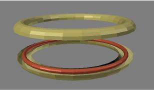
Torus Induction Project
A Magnetic Levitating Torus Rotor
Within A Non Magnetic Metal Torus
Build Start June 2022
Build Start June 2022
A short video showing the Torus Machine rotor turning but not levitating can be found on my Youtube Channel Machinery4change
This design is quite different to any of my previous ones. It is based on both the Inductrac Train and dropping a magnet down a tube. The train, or rotor, becomes a toroidal loop or ring made of magnets with alternating radial fields. The train runs within a toroidal tunnel made of aluminum.
Coils are arranged around the outside of the tunnel and drive the rotor as a BLDC motor.
Like the Inductrac Train, the rotor is on wheels initially, and should lift off the wheels at a low speed. As the speed increases, the rotor should centralize within the tunnel or tube. The magnetic fields radiating from the rotor are sweeping through the stationary tube walls. The distance from the magnet to the tube wall needs to be as large as possible, while still having the magnetic fields extend into the tube wall. The inductrac Train when at maximum speed / lift also has minimum drag. The maximum height is reached automatically, where any further increase in height would lift the train field off the conductor track.
When my Toroidal Train lifts to the center of the tube, then with any further increase in speed the field created should increase in size / strength around the tube, and hopefully will interact with the Earth's Dynamic Gravitational Field and cause the entire machine to lift. My prediction is that when the rotor lifts away from the wheels, 100% of the weight of the rotor will disappear.
The radial field magnets for the rotor are a little bit unusual, but not expensive. Each Magnet is made from 2 cylinder magnets. These are forced together with like poles together.
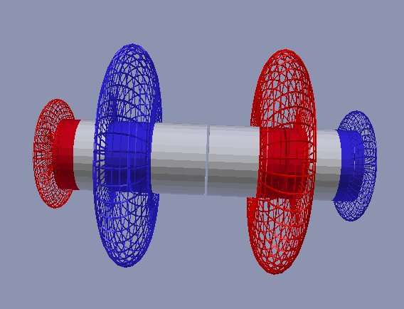
The drawing above shows 2 sets of what I call "supermagnets". Four magnets here give 2 alternating radial fields. I have made some of these from 22mm diam x 25mm long ferrite magnets. The radial fields are surprisingly strong and reach out a considerable distance.
In the center where unlike poles are attracted the field disappears. The end fields are about normal strength. When a large quantity of these sets are arranged into a ring or rotor, there are no end fields. There is a small amount of flux leakage where each super magnet is placed at a small angle to its neighbors, but does not extend far enough to interfere with the drive fields or Hall Effect sensor operation. 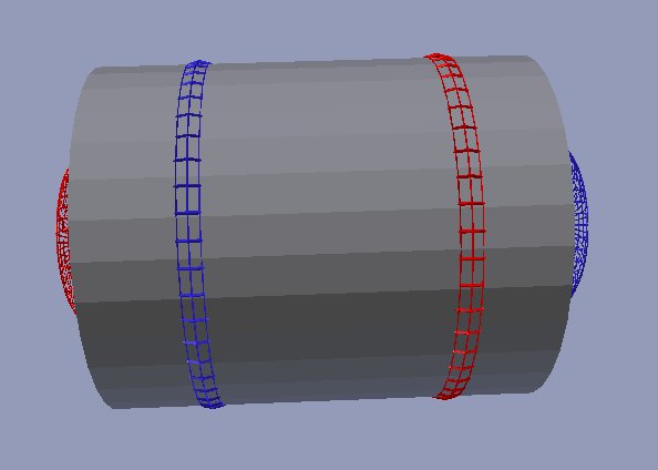
The tube is added and the fields can be seen reaching into the tube wall.

A coil is shown here in a position where maximum torque would be obtained when the coil is powered. A test setup of a similar layout gave excellent results.
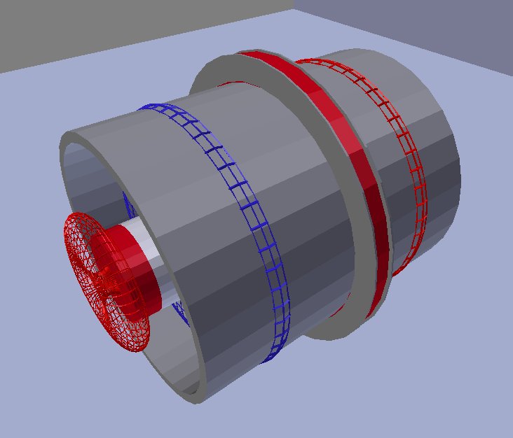
The aluminum tube I have obtained is 76mm OD x 4.5mm wall thickness. So the ID is 67mm. Dropping a pair of my supermagnets down a 1m length of this tube shows no apparent slowing from magnetic drag. With the rotor on wheels at the bottom of the tube the drag would likely be quite considerable.
The rotor has been made. It has 36 alternating poles, from a total of 72 22mm diam x 25mm long ferrite magnets. The diameter at the magnets centerline is 650mm. A bicycle rim has been used to assemble the rotor magnets on. A bike rim is not ideal but is cheap, round, non magnetic, and strong. The magnets need to be securely restrained from centrifugal force, and this means gaps for rivets or bolts. The bike rim conveniently has 36 spoke holes already accurately spaced. A better way would be a purpose made alum section formed with the opening on the inside. Magnets could be fitted with no gaps and centrifugal force would retain them in place.
Ferrite magnets have been used because they are cheap, I have them, and they have a very strong field when made into "supermagnets". Rare Earth magnets may be a better choice, and specially made curved magnets should have no flux losses.
The tube is to be cut into 27 segments, to give the correct ratio of magnets to coils. Each segment is then cut in half. Lower and upper torus halves can be fabricated from these pieces.
The upper and lower sections can be welded, but final assembly would be by mechanical fastening. This is to protect the rotor magnets from excess heat. Once the coils have been wound around the outer torus there is no easy way to dismantle the machine.
The upper and lower sections can be welded, but final assembly would be by mechanical fastening. This is to protect the rotor magnets from excess heat. Once the coils have been wound around the outer torus there is no easy way to dismantle the machine.
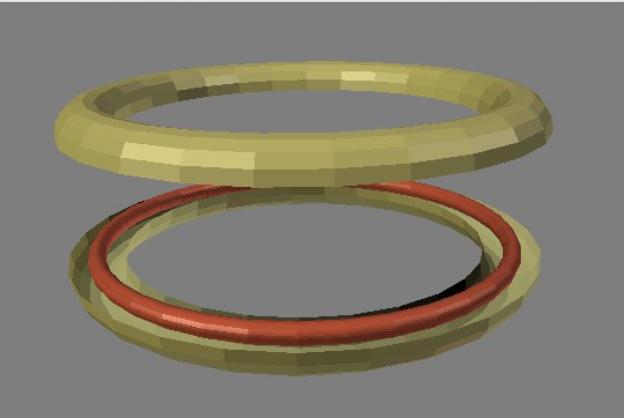
If a working prototype can be achieved, the outer torus or stator could be replicated quite easily by alum casting from a mold, die casting, or 3D metal printing. Alum is cheap and readily available as scrap, but there are many metals which may be better. If the inside major diameter is circular, not segmented, then wheels may not be needed if both the rotor and inner stator are coated with a non stick surface. This could also help by reducing air resistance.
On the machine being built, there 27 possible coil positions, one for each segment. I will use 6 of these for Low Side BLDC motor switching. Normal switching would require just 3. Another 12 coil positions will be made available for later testing to see if more shorted copper coils add to any lift capability.
On the machine being built, there 27 possible coil positions, one for each segment. I will use 6 of these for Low Side BLDC motor switching. Normal switching would require just 3. Another 12 coil positions will be made available for later testing to see if more shorted copper coils add to any lift capability.
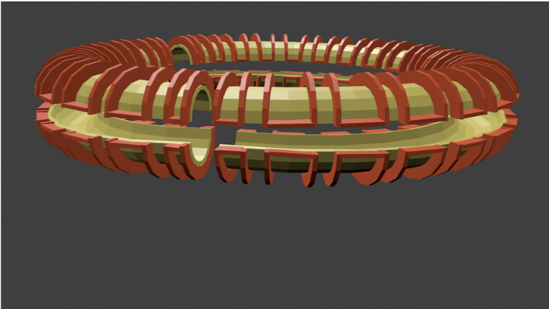
How one pattern of 120 degrees could be made into six identical parts for a complete outer torus. Spare coils could be wound with non insulated alum wire, or insulated copper wire and shorted. It may be possible to have some coils of insulated copper able to be switched from open to closed circuit. That is, if the machine can be made to hover with some coils open circuit, then closing the circuit may create a greater field, and rapid vertical acceleration may occur with no increase in rotor speed.


